Ariaboard Renesas G2E EVB Kit: Difference between revisions
| Line 29: | Line 29: | ||
| Camera|| 2-line CSI | | Camera|| 2-line CSI | ||
|- | |- | ||
| Ethernet || | | Ethernet || Realtek RTL8211E-VB-CG 10/100/1000M PHY | ||
|- | |- | ||
| UART || x5 | | UART || x5 | ||
Revision as of 22:46, 25 July 2021
Introduction
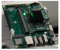
Hardware
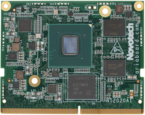
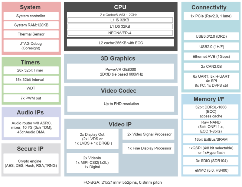
G2E Core boardFront ViewBlock DiagramSpecifications
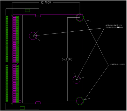
Module Size
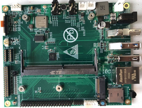
LayoutG2E EVB boardFront ViewSpecifications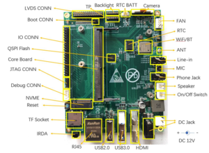
Build Your G2E ImageUbuntu 20.04 pre-install aptsapt install git build-essential flex bison Fetch RZ/G2E Linux SDKgit clone ****/rzg2-linux-sdk.git cd rzg2-linux-sdk git submodule update --init Build RZG2 Flash Burnercd rzg2-flash-writer ./build-g2e-emmc.sh Build ARM Trusted Firmwarecd arm-trusted-firmware ./build-ek874-emmc.sh Build U-Bootcd renesas-u-boot-cip ./build-g2e-emmc.sh Boot Flash Burner from serial portSet serial port of PC to 115200bps, 8N1. Set boot mode of board to download mode. Connect Debug port of board to the serial port of PC. Power on the board, then something like "please send !" will be printed on terminal. Upload file rzg2-flash-writer/AArch64_output/AArch64_Flash_writer_SCIF_DUMMY_CERT_E6300400_ek874.mot with ASCII mode. After uploading, prompt ">" will appear in terminal. Install ARM Trusted Firmware & U-Boot
Use EM_W command to write S-record file into eMMC. e.g: >EM_W
EM_W Start --------------
---------------------------------------------------------
Please select,eMMC Partition Area.
0:User Partition Area : 30535680 KBytes
eMMC Sector Cnt : H'0 - H'03A3DFFF
1:Boot Partition 1 : 16384 KBytes
eMMC Sector Cnt : H'0 - H'00007FFF
2:Boot Partition 2 : 16384 KBytes
eMMC Sector Cnt : H'0 - H'00007FFF
---------------------------------------------------------
Select area(0-2)>1 <<<< Enter "1" here
-- Boot Partition 1 Program -----------------------------
Please Input Start Address in sector :0000 <<<< Enter "0000" here
Please Input Program Start Address : E6320000 <<<< Enter "E6320000" here
Work RAM(H'50000000-H'50FFFFFF) Clear....
please send ! ('.' & CR stop load)
SAVE -FLASH.......
EM_W Complete!
eMMC Boot SettingsPlease note that for eMMC booting, the following EXT_CSD registers need to be modified: EXT_CSD[B1] = 0x0A EXT_CSD[B3] = 0x08 Use EM_SECSD command to modify EXT CSD registers: >EM_SECSD Please Input EXT_CSD Index(H'00 - H'1FF) :b1 EXT_CSD[B1] = 0x00 Please Input Value(H'00 - H'FF) :a EXT_CSD[B1] = 0x0A >EM_SECSD Please Input EXT_CSD Index(H'00 - H'1FF) :b3 EXT_CSD[B1] = 0x00 Please Input Value(H'00 - H'FF) :8 EXT_CSD[B1] = 0x08 Check BootloaderPower off the board. Set boot mode to eMMC boot. Then power on. It should be able to boot into u-boot: [ 0.000096] NOTICE: BL2: RZ G2E Initial Program Loader(CA53) [ 0.004372] NOTICE: BL2: Initial Program Loader(Rev.2.0.7) [ 0.009905] NOTICE: BL2: PRR is RZG G2E Ver.1.1 [ 0.014478] NOTICE: BL2: PLL1 nonSSCG Clock select [ 0.019327] NOTICE: BL2: Board is EK874 RZ/G2E Rev.1.0 [ 0.024502] NOTICE: BL2: Boot device is eMMC(50MHz x8) [ 0.029682] NOTICE: BL2: LCM state is CM [ 0.033647] NOTICE: BL2: 0x400000000 - 0x47fffffff, 2 GiB [ 0.039080] NOTICE: BL2: DDR1856(rev.0.12) [ 0.043231] NOTICE: BL2: [COLD_BOOT] [ 0.048483] NOTICE: BL2: DRAM Split is OFF [ 0.051179] NOTICE: BL2: QoS is default setting(rev.0.05) [ 0.056622] NOTICE: BL2: DRAM refresh interval 3.9 usec [ 0.068842] NOTICE: BL2: v1.5(release):61eac60f5-dirty [ 0.072573] NOTICE: BL2: Built : 19:44:42, Dec 16 2020 [ 0.077761] NOTICE: BL2: Normal boot [ 0.081399] NOTICE: BL2: eMMC boot from partition 1 [ 0.086539] NOTICE: BL2: Load dst=0xe6312100 src=(p:1)0x30000(384) len=0x200(1) [ 0.093922] NOTICE: BL2: Load dst=0x43f00000 src=(p:1)0x30400(386) len=0x1800(12) [ 0.101589] NOTICE: BL2: Load dst=0x44000000 src=(p:1)0x40000(512) len=0x10000(128) [ 0.110783] NOTICE: BL2: Load dst=0x50000000 src=(p:2)0x0(0) len=0x100000(2048) [ 0.139578] NOTICE: BL2: Booting BL31 U-Boot 2018.09-g3bc3f7369f-dirty (Dec 17 2020 - 16:51:50 +0900) CPU: Renesas Electronics R8A774C0 rev 1.1 Model: Silicon Linux EK874 RZ/G2E board DRAM: 1.9 GiB Bank #0: 0x048000000 - 0x0bfffffff, 1.9 GiB Watchdog: Not found by seq! WDT: watchdog@00000000e6020000 Watchdog: Started! MMC: sd@ee100000: 0, sd@ee160000: 1 Loading Environment from MMC... OK In: serial@e6e88000 Out: serial@e6e88000 Err: serial@e6e88000 Net: Error: ethernet@e6800000 address not set. eth-1: ethernet@e6800000 Hit any key to stop autoboot: 2 Build Linux Kernelcd linux-cip ./build-g2e.sh Create Linux root filesystemPrepare a SD card with capacity of 16GB or more. Use partition tool like fdisk, create 2 partitions on SD card: first partition should be FAT16/32, with size at least 64MiB, secord partition should be ext4, size should be at least 8GiB. Copy files below into first partition (replace /dev/sdb1 to the first partition of your real SD card device path): sudo -s mount /dev/sdb1 /mnt cp -v linux-cip/deploy/g2e/Image /mnt cp -v linux-cip/deploy/g2e/r8a774c0-rzg2e-novotech.dtb /mnt cp -v linux-cip/deploy/g2e/modules.tar.gz /mnt umount /dev/sdb1 exit Then create Debian 10 (Buster) rootfs: sudo -s
apt-get install qemu-user-static debootstrap schroot
mkdir debian-rootfs
cd debian-rootfs
export ROOTFS="$(pwd)"
qemu-debootstrap --arch arm64 --variant buildd --include=ca-certificates,apt,wget,sudo,debootstrap,isc-dhcp-client,nano,network-manager buster "${ROOTFS}" http://deb.debian.org/debian
chroot "${ROOTFS}"
passwd root
#Input your root password
exit
tar -xf ../linux-cip/deploy/g2e/modules.tar.gz
tar -czpf ../debian-buster-rootfs.tar.gz .
exit
Mount and extract rootfs to the second partition of your SD card (replace /dev/sdb2 to your one). sudo -s mount /dev/sdb2 /mnt tar -xpzf debian-buster-rootfs.tar.gz -C /mnt # Copy rootfs to SD card so that you can install it to eMMC (Optional): cp -v debian-buster-rootfs.tar.gz /mnt umount /dev/sdb2 exit Boot kernel & rootfs from SD cardAt u-boot auto booting count down, press enter to break into u-boot command-line. Use commands below to boot from SD card: setenv bootargs 'root=/dev/mmcblk0p2 rootwait rw' fatload mmc 0:1 0x48080000 Image; fatload mmc 0:1 0x48000000 r8a774c0-rzg2e-novotech.dtb; booti 0x48080000 - 0x48000000 The device path of SD card is /dev/mmcblk0, and the path of eMMC is /dev/mmcblk2. Kernel and rootfs can be written into eMMC with the same partition structure as SD card. Using GPIO
You use user level interfaces in You can check GPIO stats by reading sudo cat /sys/kernel/debug/gpio Using Audio SoCAt first running, ALSA should be configured with the commands below: amixer cset name="HP Playback Switch" on amixer cset name="HPO MIDAC1 Switch" on amixer cset name="Stereo DAC MIXL DAC L1 Switch" on amixer cset name="Stereo DAC MIXR DAC R1 Switch" on amixer cset name="DAC MIXL INF1 Switch" on amixer cset name="DAC MIXR INF1 Switch" on amixer cset name="DAC MIXL Stereo ADC Switch" off amixer cset name="DAC MIXR Stereo ADC Switch" off amixer cset name="ADC Capture Switch" on amixer cset name="Stereo1 ADC MIXL ADC1 Switch" on amixer cset name="Stereo1 ADC MIXR ADC1 Switch" on amixer cset name="RECMIXL INL1 Switch" on amixer cset name="RECMIXR INR1 Switch" on amixer cset name="RECMIXL BST1 Switch" on amixer cset name="RECMIXR BST1 Switch" on alsactl store If you are using non-standard Linux distributions (like customized Yocto or buildroot), you should write the mixer configurations in startup script. Using CameraCamera Module: Sony IMX219 Use commands below to initialize media controller: FHD(1920x1080) mode: media-ctl -d /dev/media0 -r media-ctl -d /dev/media0 -l "'rcar_csi2 feaa0000.csi2':1 -> 'VIN4 output':0 [1]" media-ctl -d /dev/media0 -V "'rcar_csi2 feaa0000.csi2':1 [fmt:SRGGB8_1X8/1920x1080 field:none]" media-ctl -d /dev/media0 -V "'imx219 0-0010':0 [fmt:SRGGB8_1X8/1920x1080 field:none]" VGA(640x480) mode: media-ctl -d /dev/media0 -r media-ctl -d /dev/media0 -l "'rcar_csi2 feaa0000.csi2':1 -> 'VIN4 output':0 [1]" media-ctl -d /dev/media0 -V "'rcar_csi2 feaa0000.csi2':1 [fmt:SRGGB8_2X8/640x480 field:none]" media-ctl -d /dev/media0 -V "'imx219 0-0010':0 [fmt:SRGGB8_1X8/640x480 field:none]" Camera device will be /dev/video0 on Debian rootfs, and /dev/video8 on Yocto rootfs. Camera subdev device will be /dev/v4l-subdev1 on Debian rootfs, and /dev/v4l-subdev18 on Yocto rootfs. You can use You can use commands below to configure camera parameters (on Debian rootfs): #Set exposure v4l2-ctl -d /dev/v4l-subdev1 --set-ctrl exposure=1600 #Set analog gain v4l2-ctl -d /dev/v4l-subdev1 --set-ctrl analogue_gain=232 #Check camera controllers v4l2-ctl -d /dev/v4l-subdev1 --list-ctrls Use GStreamer to get a photo (on Debian rootfs): gst-launch-1.0 v4l2src device=/dev/video0 num-buffers=1 ! video/x-bayer,format=rggb,width=1920,height=1080,framerate=30/1 ! bayer2rgb ! videoflip video-direction=4 ! videoflip video-direction=5 ! jpegenc ! filesink location=camsnap.jpg Use GStreamer to show video from camera (on Yocto rootfs, need Wayland support): gst-launch-1.0 v4l2src device=/dev/video8 io-mode=dmabuf ! video/x-bayer,format=rggb,width=640,height=480,framerate=30/1 ! bayersink Known problemsWiFi module does not support random MACBy default, Network Manager will use random MAC for better security, somehow the module used on this board does not support it. You should disable it by edit file [device] wifi.scan-rand-mac-address=no Set MAC address of ethernet cardThere is no EEPROM or SPI Flash to save MAC address for ethernet card. So you can set MAC address by yourself. e.g. Using Network Manager: sudo nmtui Edit your ethernet connection, unfold ETHERNET option, set "Cloned MAC address" to the address you want. Then exit the tool to save your settings. Or you can set MAC address in u-boot, press Enter key when u-boot is waiting for interrupting, then set MAC address with commands below: setenv ethaddr "AC:F3:5F:1E:87:53" saveenv You can replace the address with the one you want. No Graphic Accelerations on Debian rootfs2D/3D Graphic Accelerations are only supported in Renesas's customized Yocto, and only Wayland is supported. No Bayer Color Encoding SupportSome cameras (like Sony IMX219) can only output RAW bayer video data, which is not supported by hardware encoders on the board. Even through you can convert color space with GStreamer element like bayer2rgb, it will cost lots of CPU resources and RAM bandwidth. TestEnable Speaker Outputecho 393 > /sys/class/gpio/export echo out > /sys/class/gpio/gpio393/direction echo 1 > /sys/class/gpio/gpio393/value gst-launch-1.0 audiotestsrc ! audioconvert ! audioresample ! autoaudiosink Use Micarecord -Dhw:0,0 -f S16_LE -t wav -r44100 -c 2 record.wav Note: not support sample rate 48000 RS485 PortTTY: ttySC2 Note: 1. disable flow control Enable Developer options in AndroidSteps: 1. Find item "Buile number" (Path: Settings -> About tablet -> Build number) 2. click it 10 times How to adb connect device through networkDebug console steps: 1. su 2. setprop service.adb.tcp.port 5555 3. stop adbd 4. start adbd ADB connect command: 1. adb connect <Device IP> |
